©
Electrical Research and Development Association (ERDA)
.
All rights reserved.
Designed and Developed by
Trizone India
i) Root Cause Analysis of Failed Evaporator Coil of Boiler
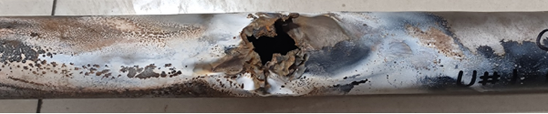
Root cause analysis of failed evaporator coil of boiler was carried out for one of the thermal power plants. The evaporator coil was found punctured after 24 years of service life. The detailed analysis of failed evaporator coil was carried out using techniques such as visual examination, fractography, chemical analysis (OES), microstructure analysis using optical and scanning electron microscopy (SEM), mechanical testing for strength and hardness and Energy Dispersive Spectroscopy (EDS) for deposit analysis.
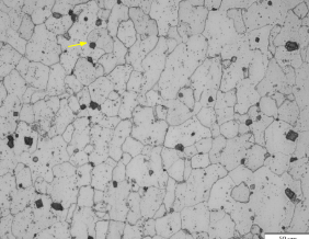
It was observed that coil ruptured with window open fracture appearance with slight bulging of coil along the length of tube. Chemical composition of evaporator coil conforms to the SA 210 Gr. A1 grade. Microstructure of coil showed presence of spherodize structure and voids/cracks along the grain boundaries, indicating substantial thermal degradation due to overheating. Tensile strength of coil also observed lower compared to specification requirement which supports the observed thermal degradation of structure. EDS analysis of inner wall deposits showed presence of S, P, Na, Mg, Cl, K and Cu which indicate possibility of corrosion resulted in metal thinning on inner wall of coil.
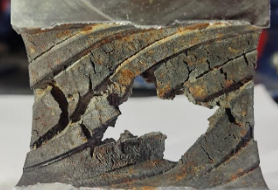
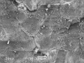
The fracture examination showed presence of multiple longitudinal cracks on inner and external wall. SEM micrographs at higher magnification showed crack propagation along the boundaries of grain like structure which might be linked with voids/cracks observed in microstructure along the ferrite grain boundaries.
It was inferred from the detailed analysis that the failure of evaporator coil occurred due to overheating. The spherodize microstructure along with voids/cracks at the grain boundaries and presence of multiple longitudinal cracks confirms the thermal degradation of structure due to overheating.
As the overheating of coil can occur due to high temperature exposure because of hindrance to heat transfer from oxide scale and deposits, obstruction to water flow etc., it is recommended to ensure the proper water flow inside tubes, control water chemistry to reduce deposits and water side oxidation/corrosion and carry out regular condition monitoring (Wall thickness, in-situ metallography, hardness etc.) of coils to prevent the failures.
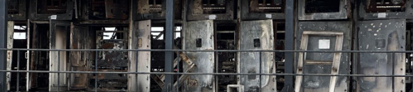
ii) Root Cause Analysis of Electrical Fire at 33 kV HT Panels
Root cause analysis (RCA) of electrical fire incident at 33 kV HT panel of solar power plant was carried out. The panels were approximately 2 years old and consist of Vacuum Circuit Breakers, CTs, PTs, Relays, Bus bar, Cables, Surge Arrester, etc.. Team of ERDA experts visited the site where electrical fire incident happened. ERDA team collected data, interviewed the witness and collected visual evidences during the visit. Some fire affected material was also received at ERDA for further analysis. The fire was so devastating that practically burned major parts of all the panels and there was no possibility of data collection from panel’s protective relays.
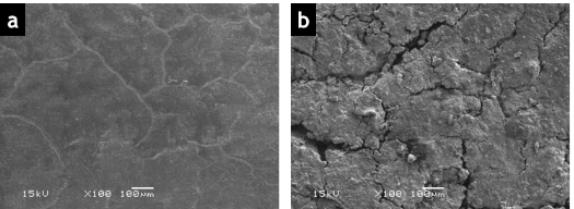
Laboratory analysis of similar incident showed localised electrical tracking in bus bar sleeves and inter-panel seal. Initiation of electrical tracking and later growth resulting in cracks in the bus-bar sleeve was visible in Scanning Electron Microscope (SEM) images, as shown in Figure (ii)(2). The electrical tracking of the insulation may have resulted from local saline and humid atmosphere. The growth of electrical tracking can have resulted in electrical arcing resulting in fire. Further this fire caused overheating and degradation of CMC sheets, cast resin CT/PT, fuses, control wiring, relays etc. The high energy of the arcing resulted in melting of metal connection holding the vacuum interrupter to trip breaker at grid end substation. Based on the sequence of event, available data from the customer and analysis of materials at ERDA, the RCA was concluded with recommendations to avoid such fire incidents in future.
i) Method validation reportsvalidation and development of spreadsheet operating system for preparation of Energy Audit report of Thermal Power Plants, Process Industries, Manufacturing Industries, DISCOMs and Commercial Buildings
Considering the vast potential of energy savings and sue of energy efficiency in various sectors of industries, the Government of India enacted the Energy Conservation Act, 2001. The Act provides for a legal framework, Institutional arrangement and a regulatory mechanism at the Central and State level to embark upon energy efficiency drive in the country. A process industry includes various interlinked processes and equipment which uses various process fluids or process materials and various forms of energy such as electrical, thermal, chemical, mechanical, etc. from various energy sources. Energy audits are essential for identifying energy-saving opportunities and improving energy efficiency in industries, power plant and other facilities. However, a valid energy audit procedure and excel sheets with possible saving opportunities in various conditions can lead to consistent results and reliable recommendations, which can improve the effectiveness of energy-saving efforts. This comprehensive software for energy audit covering analysis of all sectors like Thermal Power plants, Process Industries and Manufacturing Industries.
Energy auditing procedures and standardization software covers the various systems in Power plant, Process industries and Buildings as follows:
Energy auditing procedures and standardization software also covers DISCOMs for annual accounting and energy audit as per notification of BEE is as follows:
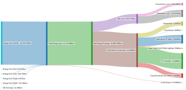
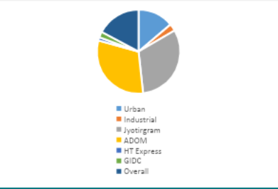
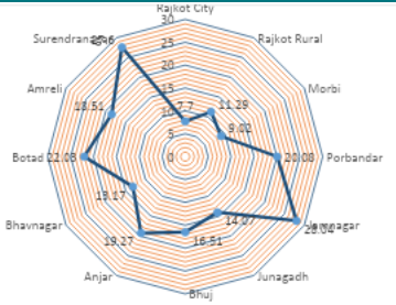
This Software helps to understand the complete technical scenario of DISCOM and shows the possible areas of improvement. It also helps to comply the mandates of BEE about report submission on annual basis for DISCOM. Following are some indicative outcomes from software.
ii) PD Sensing Solution for MV Application
New Product Technologies section of R&D division of ERDA completed Contract Research Project titled “PD Sensing Solution for MV Application”. This project was sponsored by a leading company. The objective of this project was to carry out literature survey on Partial discharge detection for medium voltage switchgear application and provide technological solution for the same. In depth study of various partial discharge techniques available globally was carried out and solutions were proposed as an outcome of the project.
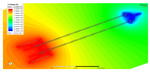
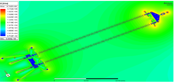
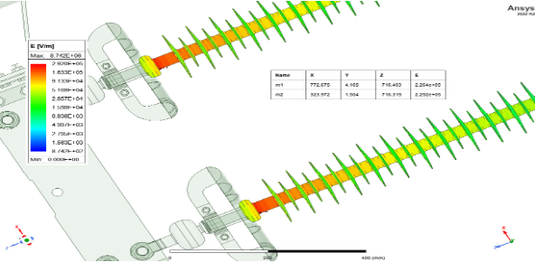
i) Electrical Field Analysis of 400kV -160kN silicon Composite Insulator by FEM approach
A Silicon Composite Insulator Design and Analysis study was undertaken for the client by using the Finite Element Method Approach. Specifically, the work involved detailed electrostatic field mapping (Electric Field and Voltage) at RMS Voltage level on Silicon Composite Insulator. ERDA have performed this study by using ANSYS Maxwell 3D software and provided the result of Electric field Strength at various locations across the Insulator profile.
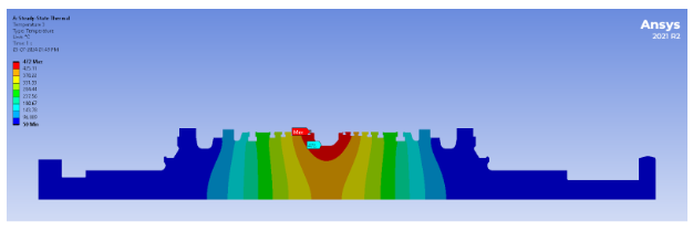
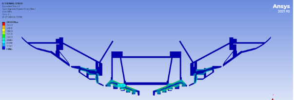
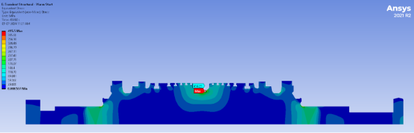
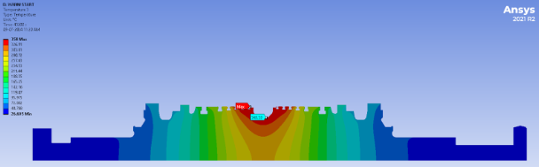
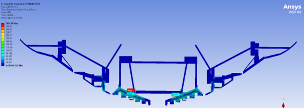
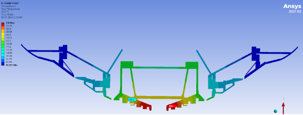
ii) Residual Life Assessment (RLA) of 210 MW Low Pressure Turbine by FEM Approach:
FEM Analysis of Low Pressure Turbine Rotor and casing of 210 MW Thermal Power Plant was undertaken for client to determine remaining life in creep and fatigue. ERDA has performed this study by using ANSYS Workbench in both static and transient condition.
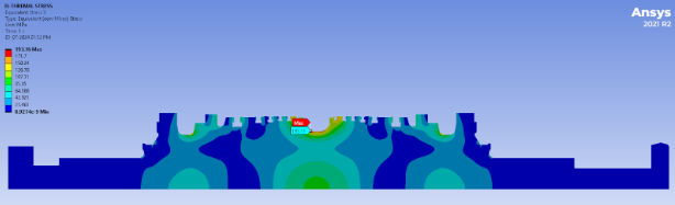
Static Analysis was done by using steady-state thermal to determine creep life of Rotor and Casing of Low Pressure Turbine.
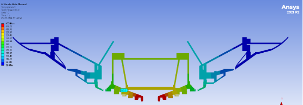
Transient Analysis was done by using transient Thermal to determine fatigue life of Rotor and casing of Low Pressure Turbine in cold start, warm start and hot start Conditions.
The results obtained from steady-state thermal and transient thermal Analysis of Turbine rotor and casing wassis used in Robinson-Miner’s formula to calculate remaining life of component as per below table.
| The Total Robinson Miner Sum is given below | |||||
|---|---|---|---|---|---|
| Component | M creep | M fatigue | M Expended Total | M Remaining | Life remaining (Year) |
| LP Rotor | 0.24 | 0.06 | 0.30 | 0.70 | ≈26 |
| LP Casing | 0.01 | 0.08 | 0.09 | 0.91 | ≈135 |
Conclusions:
The results of FEA analysis for LP Rotor & Casing show that 30% & 9% of creep and low cycle fatigue life has been expended respectively. The balance life of 70% & 91% of Rotor and casing translates into a useful operational life of another 26 years and 135 years respectively assuming that the machine will be operated maintaining similar parameters and stop/ start schedules as done in the past.
©
Electrical Research and Development Association (ERDA)
.
All rights reserved.
Designed and Developed by
Trizone India