©
Electrical Research and Development Association (ERDA)
.
All rights reserved.
Designed and Developed by
Trizone India

A. Root Cause Analysis (RCA)
i) Root Cause analysis of Failed ACSR Panther Conductor of 100 kV DC line
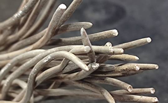
Root Cause Analysis (RCA) of snapped ACSR conductor of 100 kV DC line was carried out for one of the utility. Failed conductor was investigated using techniques such as visual examination, fractography analysis, optical and scanning electron microscopy (SEM) and mechanical testing. It was observed that conductor snapped with fracture of aluminium and steel wires. Material analysis of aluminium wire and steel did not indicate abnormality in material composition, microstructure, and dimensions. Both wires also met the mechanical property requirement of breaking load as per IS 398 specification. Loose deposits of S, Cl, Na, Ca and K observed on Al and steel wire but no significant metal loss due to corrosion and dimensional changes observed.
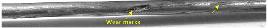
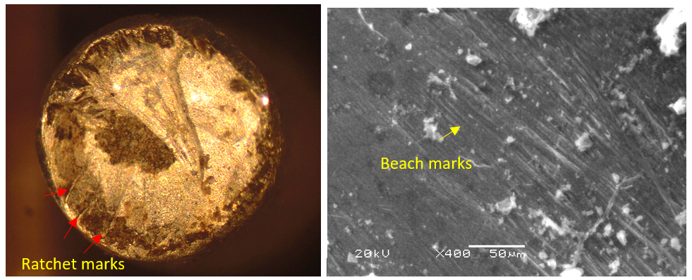
Visual and fractography analysis indicate the presence of wear marks along with cracks on fractured aluminium wires. The fracture surface show flat appearance for many failed aluminium wires with ratchet marks and beach marks indicating fatigue failure. The crack initiation clearly observed on fracture surface originated from the wear region at the surface of aluminium wires. The fracture surface of steel wires indicate cup and cone ductile fracture appearance.
It was inferred from the analysis that the failure of ACSR conductor occurred due to fretting fatigue failure of aluminium wires. The progressive damage of conductor with time possibly occurred due to cyclic loading from wind vibrations. The wind vibrations acting on conductor during operation might have caused bending stress and torque on conductor strands which led to micro slip of strands at contacts, resulted in wear/metal loss. Then under cyclic loading of wind vibration, cracks initiated at the wear marks, propagated and fractured the aluminium wires. After fracture of aluminium wires, finally steel wires failed in ductile cup and cone manner. As the failure of ACSR conductor occurred due to fretting fatigue, recommendations were given regarding condition assessment and vibration analysis.
ii) Root Cause analysis of Failed 765 kV Composite Insulators
Failed composite insulators (Silicone Rubber Insulators) located on 765 kV transmission line were received for Root Cause Analysis (RCA) of failures. The insulators failed after service life of 4 years. The RCA was executed by doing visual analysis, microscopic observations, material testing and FEM analysis of electric field.
The insulators were located in relatively less polluted region. The insulators did not show accumulation of pollutants on the silicone rubber housing. One of the failure insulators showed erosion marks related to corona discharges in insulator tri-junction and silicone rubber shades. Furthermore some of the silicone shades showed microscopic cracks indicating degradation. External degradation of the insulator indicated failure due to corona discharges on the silicone rubber housing. One failed insulator also showed internal degradation on the tower end. The insulator also showed poor adhesion with composite rod indicating flash under responsible for failure. Suitable recommendations related to monitoring of transmission line and quality evaluation of composite insulator was given to customer.
B. R&D Project
A sponsored project on silicone rubber analysis was successfully completed, with the final report submitted to the client. The analysis involved ERDA’s in-house developed methodology along with Broadband Dielectric Spectroscopy (BDS). ERDA’s method proved effective in characterizing a variety of silicone rubber compounds, while the BDS results highlighted variations in dielectric parameters based on sample conditioning.
C. Testing / Simulation Study Conducted for Customer
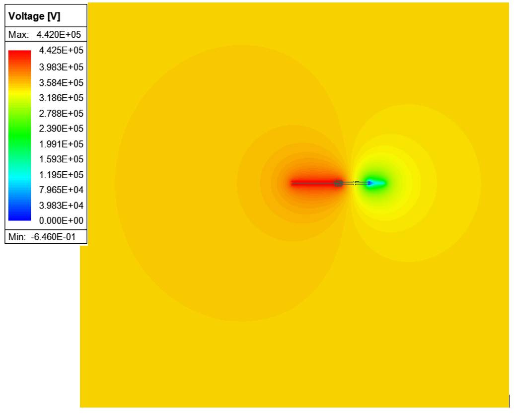
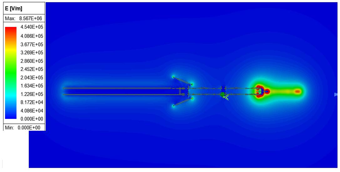
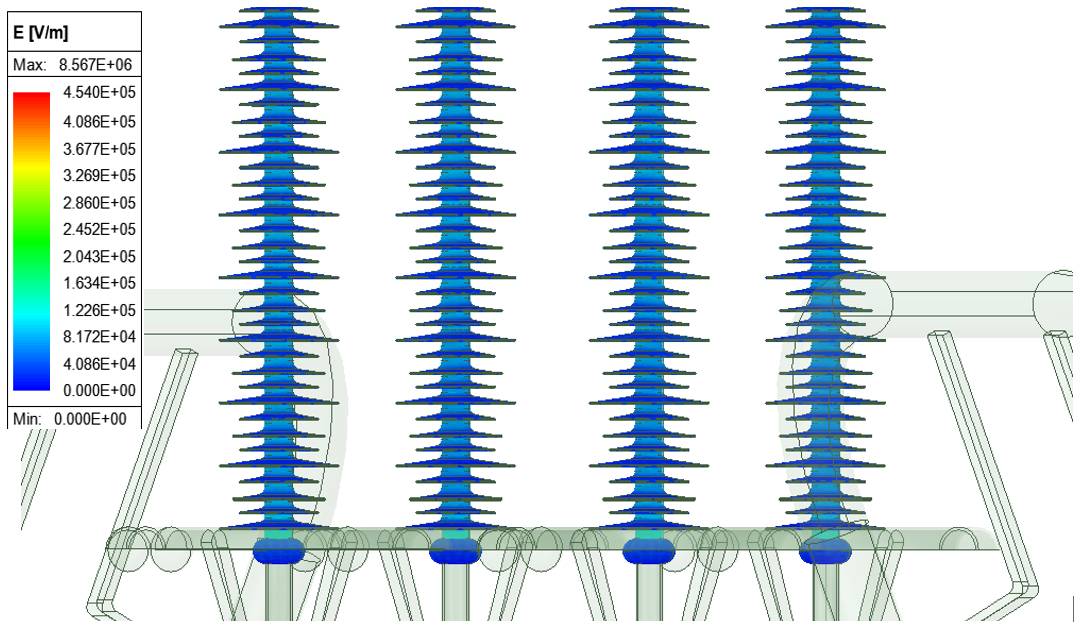
i) Electrical Field Analysis of 765kV -210kN silicon Composite Insulator by FEM approach
A Silicon Composite Insulator Design and Analysis study was undertaken for the client by using the Finite Element Method Approach. Specifically, the work involved detailed electrostatic field mapping (Electric Field and Voltage) at RMS Voltage level on Silicon Composite Insulator. This study was perfromed by using ANSYS Maxwell 3D software and provided the result of Electric field Strength at various locations across the Insulator profile.
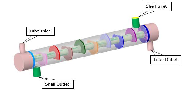
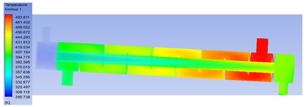
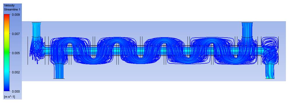
ii) CFD Analysis of Shell and Tube Type Heat Exchanger
Computational fluid dynamic (CFD) Analysis for Shell and Tube Heat Exchanger was undertaken to know the performance of Heat exchanger in various conditions of fluid flow and various design parameter. ERDA has performed this study in ANSYS Fluent solver and 3D modelling has done in Space-claim. Provide the result of Temperature Distribution, Velocity Distribution in the form of Contour, Vector, Streamline as well as Volume Rendering of Temperature and Velocity in whole Domain.
iii) Protection Audit as per Ramkrishna Committee, Indian Electricity Grid Code (IEGC)
Protection audit as per Ramkrishna Committee, Indian Electricity Grid Code (IEGC) carried out as below:
D. Patent Granted/Filled
Following mentioned patents were filed/granted for the technologies developed by ERDA.
i) Title: A Reversible Aluminium Ion Battery Energy Storage Technology
Inventor: Dr. Vilas Gunjal, Dr. Nitin Shingne, Dr. Uday Puntambekar, Dr. Satish Chetwani
Application No: 202521008561
Date of filing: 02/02/2025
ii) Title: A Voltage Tester Device / System for Safety Application in Electrical Panel and Method Thereof
Inventor: Mr. Hardik Khambhadiya, Mr. Asheesh Dhaneria, Dr. Satish Chetwani
Indian Patent Number: 564683
Date of Grant: 31/03/2025
©
Electrical Research and Development Association (ERDA)
.
All rights reserved.
Designed and Developed by
Trizone India